VGAlib3
What follows is the IMPLEMENTATION MODULE for the VGAlib3 library for FST Modula-2. Have fun studying the source. It took me quite some time to get this thing going.... :o)
IMPLEMENTATION MODULE VgaLib3
IMPLEMENTATION MODULE VgaLib3;

(*  This is FREE software, as described in the GNU General Public Licences.
    Therefore it comes WITH THE FULL SOURCES. Please feel free to improve this
    code when necessary. You OWN this code.

    I would appreciate that people let in this message when extending this
    library, as a small tribute to me (for laying the foundation).

    In case people need extra information, contact me via:

        snail mail: Jan Verhoeven, 5012 GH 272, The Netherlands
   electronic mail: mocka@yahoogroups.com

    I remain full copyrights to these sources. If you want to send me a small
    "thanks", please send me a postcard of your hometown to the above shown
    snailmail address. Yes it is in code; the internal code of our national
    mail deliverer.

    Use this software at your own risk. Please find yourself a GNU GPL if you
    are in any doubt. I use these functions for all my own software, but there
    is NO GUARANTEE OF ANY KIND covering it.            *)
Some IMPORTing and vars are needed
First we do some IMPORTING. Some of these should not be necessary but for speed-reasons I did them anyway. An example is SHR (shift right) which might as well been implemented as a BITSET operation, but this is done in pure inline ASM.
FROM    barith      IMPORT  shr;
FROM    SYSTEM      IMPORT  ASSEMBLER, ADDRESS;
FROM    FileSystem  IMPORT  File, Lookup, Close, ReadNBytes, Response;
FROM    InOut       IMPORT  WriteString;
FROM    Strings     IMPORT  Length;
FROM    Storage     IMPORT  Available, ALLOCATE, DEALLOCATE;
FROM    System      IMPORT  Terminate;

VAR     fp      : File;
        Bread   : CARDINAL;
        BitMap  : ADDRESS;
So far the variables and code re-using. Time for some new code:
The code starts. First define some low level functions
PROCEDURE   SetVGA (NewMode : CARDINAL) : CARDINAL;     (*  Set screen to VGA mode NewMode  *)
                                                        (*  Return current mode             *)
VAR     OldMode     : CARDINAL;

BEGIN
    NewMode := NewMode MOD 256;
    ASM
        PUSH BP
        MOV  AH, 0FH
        INT  010H
        MOV  OldMode, AL
        MOV  AX, NewMode
        INT  010H
        POP  BP
    END;
    RETURN OldMode
END SetVGA;
When doing things with INT 0x10, always save the basepointer register (BP) since it is not sure it remains the
same. And the FST compiler uses it a lot, so don't take the risk.
Mixing ASM and Modula-2
PROCEDURE   SetColour (Foreground, Background   : COLOUR);
                                            (*  Define colour to work with.     *)
VAR     Col     : CARDINAL;

BEGIN
    Col := ORD (Foreground) + 16 * ORD (Background);
    ASM
        MOV  DX, 03C4H          (* VGA controller port *)
        MOV  AH, Col
        MOV  AL, 2
        OUT  DX, AX
    END;
END SetColour;
This is one of the things what I like in FST Modula-2: perfect mix of high level coding and assembly support.
No fancy variable fetching in ASM. Just do some in Modula and the rest Inline. The one line of Modula-2 here
is used to fill a variable with a number, instead of two enumerated values.
PROCEDURE   SetMask (Mask : CHAR);          (*  Set up mask for plotting in VGA memory.  *)

BEGIN
    ASM
        MOV  DX, 03CEH          (* VGA controller port *)
        MOV  AH, Mask
        MOV  AL, 8
        OUT  DX, AX
    END;
END SetMask;
The graphical functions start here: Plot a dot
This is where the actual graphics action routines start. Before this were only support and kernel routines.
Now we start building functionality.
We start off with the PLOT function. It plots one point at position (CurX, CurY) in the right colour.
PROCEDURE   Plot (VAR InWin : WinData);     (*  Plot point on CurX, CurY.   *)

VAR x, y    : CARDINAL;

BEGIN
    x := InWin.CurX + InWin.TopX;
    y := InWin.CurY + InWin.TopY;

    ASM
        MOV  AX, 0A000H
        MOV  ES, AX         (* Set up segment register *)
        MOV  CX, x
        AND  CX, 7          (* Which bit to plot? *)
        MOV  AH, 80H
        SHR  AH, CL         (* Compose plotting mask *)
        MOV  AL, 8
        MOV  DX, 03CEH
        OUT  DX, AX         (* Set plottingmask *)
        MOV  AX, y          (* Calculate offset in Video RAM *)
        MOV  BX, AX
        ADD  AX, AX
        ADD  AX, AX
        ADD  AX, BX         (* AX := 5 * Y *)
        MOV  CL, 4
        SHL  AX, CL         (* AX := 16 * 5 * Y *)
        MOV  BX, x
        SHR  BX, 1
        SHR  BX, 1
        SHR  BX, 1
        ADD  BX, AX         (* plus X / 8 *)
        MOV  AL, ES:[BX]
        MOV  AL, 0FFH
        MOV  ES:[BX], AL    (* and plot it *)
    END;
END Plot;
The plotting routine is based upon the following:
I refer to the definition of the Window Data, which is given in the DEFINITION MODULE:
      WinData = RECORD
                   TopX, TopY, Width, Height,
		   CurX, CurY, DeltaX, DeltaY,
                   Indent                          : CARDINAL;
		   BoxCol, TexCol, BckCol, MnuCol  : COLOUR;
		END;
This RECORD describes the following aspects of the screen we are working in:
| TopX | This is the "x" (or horizontal) value of the top right hand corner of the active window |
| TopY | The "y" (or vertical) value of the top right hand corner of the active window |
| Width | The width of this window, in pixels |
| Height | The height of the window in pixels |
| CurX | The value of the "x" coordinate within this window |
| CurY | Value of "y" within this window |
| DeltaX | Used by line drawing routines to find out how many pixels to draw horizontally |
| DeltaY | Used by line drawing routines to find out how many pixels to draw or move up |
| Indent | This is the minimum amount of whitespace there must be between text and either border |
| BoxCol | Colour of the lines around the current window |
| TexCol | Colour of the text that will be printed now |
| BckCol | Colour of the background in this window |
| MnuCol | Colour of the menu-bar (not used yet) |
Each window has it's own WinData structure. Some windows even have two or more WinData records which can be handy if you need to do different things with one window. If a window needs no border, just have the BoxCol identical to the BckCol.
In an application program (about the Liedetector, called LDA04) I have set up a LED display on screen. In it, each digit has it's own WinData record, so that the decimals had another colour from the integers.
Each WinData record is an entity. It keeps track of the current "x" and "y" coordinates and all the colours. This makes programming a lot easier and making a user interface is also a piece of cake now.
The following routine comes very close to the Plot routine: UnPlot. A keen programmer could have merged the two, but I'm not keen.
PROCEDURE UnPlot (VAR InWin : WinData);         (*  Erase pixel on CurX, CurY.  *)

VAR x, y    : CARDINAL;

BEGIN
    x := InWin.CurX + InWin.TopX;
    y := InWin.CurY + InWin.TopY;

    ASM
        MOV  AX, 0A000H
        MOV  ES, AX         (* Set up segment register *)
        MOV  CX, x
        AND  CX, 7          (* Which bit to plot? *)
        MOV  AH, 80H
        SHR  AH, CL         (* Compose plotting mask *)
        MOV  AL, 8
        MOV  DX, 03CEH
        OUT  DX, AX         (* Set plottingmask *)
        MOV  AX, y          (* Calculate offset in Video RAM *)
        MOV  BX, AX
        ADD  AX, AX
        ADD  AX, AX
        ADD  AX, BX         (* AX := 5 * Y *)
        MOV  CL, 4
        SHL  AX, CL         (* AX := 16 * 5 * Y *)
        MOV  BX, x
        SHR  BX, 1
        SHR  BX, 1
        SHR  BX, 1
        ADD  BX, AX         (* plus X / 8 *)
        MOV  AL, ES:[BX]
        MOV  AL, 0
        MOV  ES:[BX], AL    (* and erase it *)
    END;
END UnPlot;
Line drawing
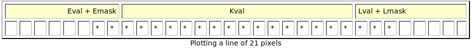
Now that we can plot pixels, it should be no big deal to draw lines. That is true, but for long lines I want to plot 8 pixels at once, freeing up lots and lots of time to do sensible things, like waiting for the user to move the mouse or press a key. :o)
In order to find the optimum linedrawer I set up a condition:
Anyway: for the long line plotting there are some special vales needed:
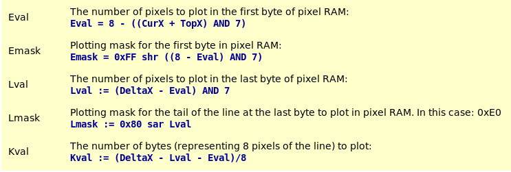
OK, the formulas have a high assembly language content syntax, but they should be understandable by most of the programmers.
PROCEDURE DrawH (VAR InWin : WinData; Flag : BOOLEAN);

(*  Draw a horizontal line from CurX, CurY for DeltaX pixels.  *)

VAR Index, Stop         : CARDINAL;
    x, dx, y, Kval      : CARDINAL;
    Emask, Lmask, Val   : CHAR;

BEGIN
    IF Flag THEN        (* Flag = TRUE => Plot, else UnPlot *)
        Val := 0FFX;
    ELSE
        Val := 0X;
    END;
    IF InWin.DeltaX < 18 THEN
        FOR Index := 0 TO InWin.DeltaX DO       (* For short lines *)
            Plot (InWin);
            INC (InWin.CurX);
        END;
    ELSE
         x := InWin.TopX + InWin.CurX;          (* For long lines *)
         y := InWin.TopY + InWin.CurY;
        dx := InWin.DeltaX;
        ASM
            MOV  AX, 0A000H
            MOV  ES, AX         (* Set up segment register *)
            MOV  CX, x
            AND  CX, 7
            MOV  BX, 8
            SUB  BX, CX
            MOV  AL, 0FFH
            SHR  AL, CL
            MOV  Emask, AL      (* compose plotting mask *)
            MOV  CX, dx
            SUB  CX, BX
            MOV  AX, CX
            AND  AX, 7
            PUSH AX             (* Save L-val *)
            SUB  CX, AX
            SHR  CX, 1
            SHR  CX, 1
            SHR  CX, 1
            MOV  Kval, CX
            MOV  AL, 0
            POP  CX             (* retrieve L-val *)
            JCXZ L0
            MOV  AL, 080H
        L0: DEC  CX
            SAR  AL, CL
            MOV  Lmask, AL

            MOV  AX, y              (* Calculate offset in Video RAM *)
            MOV  BX, AX
            ADD  AX, AX
            ADD  AX, AX
            ADD  AX, BX             (* AX := 5 * Y *)
            MOV  CL, 4
            SHL  AX, CL             (* AX := 16 * 5 * Y *)
            MOV  BX, x
            SHR  BX, 1
            SHR  BX, 1
            SHR  BX, 1
            ADD  BX, AX             (* plus X / 8 *)

            MOV  AH, Emask
            MOV  DX, 03CEH
            MOV  AL, 8
            OUT  DX, AX             (* Set plotting mask *)

            MOV  AL, Val
            MOV  AH, ES:[BX]
            MOV  ES:[BX], AL        (* Do the plotting ... *)

            INC  BX
            MOV  CX, Kval
            JCXZ L2
            MOV  AX, 0FF08H
            OUT  DX, AX
            MOV  AH, Val
        L1: MOV  AL, ES:[BX]
            MOV  ES:[BX], AH
            INC  BX
            LOOP L1
        L2: MOV  AH, Lmask
            MOV  AL, 8
            OUT  DX, AX
            MOV  AL, ES:[BX]
            MOV  AL, Val
            MOV  ES:[BX], AL
        END;
        INC (InWin.CurX, dx);
    END;
END DrawH;
So far the horizontal lines. For vertical lines it's easy: optimizations are not possible. So we just need to
plot each pixel one by one. The accompanying routine is very simple and uses the brute force of assembly
language:
PROCEDURE DrawV (VAR InWin : WinData);

(*  Draw a vertical line from CurX, CurY for DeltaY pixels. 100% optimized for speed.  *)

VAR x, y, dy    : CARDINAL;

BEGIN
     x := InWin.CurX + InWin.TopX;
     y := InWin.CurY + InWin.TopY;
    dy := InWin.DeltaY;
    ASM
        MOV  AX, 0A000H
        MOV  ES, AX         (* Set up segment register *)
        MOV  CX, x
        AND  CX, 7          (* Which bit to plot? *)
        MOV  AH, 80H
        SHR  AH, CL         (* Compose plotting mask *)
        MOV  AL, 8
        MOV  DX, 03CEH
        OUT  DX, AX         (* Set plottingmask *)
        MOV  AX, y          (* Calculate offset in Video RAM *)
        MOV  BX, AX
        ADD  AX, AX
        ADD  AX, AX
        ADD  AX, BX         (* AX := 5 * Y *)
        MOV  CL, 4
        SHL  AX, CL         (* AX := 16 * 5 * Y *)
        MOV  BX, x
        SHR  BX, 1
        SHR  BX, 1
        SHR  BX, 1
        ADD  BX, AX         (* plus X / 8 *)
        MOV  CX, dy
    L0: MOV  AL, ES:[BX]
        MOV  AL, 0FFH
        MOV  ES:[BX], AL    (* and plot it *)
        ADD  BX, 80
        LOOP L0
    END;
    INC (InWin.CurY, dy);
END DrawV;
Writing text
Now that we can draw lines and hence make boxes, it's time to put some readable data into these boxes. For this we need to be able to:
The routine also handles the following conditions:
| Condition | Action |
|---|---|
| Linefeed | The cursor is placed one line of text lower. This is NOT one pixel, but the number of lines of one pixel. In this case: 16. |
| Carriage Return |
The cursor is placed at the start of the line for text. This means that the cursor is put at the position defined by 'Indent'. |
| Indent | The software checks if the upcoming token does not pass the pixel (TopX + Width - Indent) meaning that the right window border is never overwritten by text or tokens. |
For the rest it's all quite straightforward. Analogous to line drawing we define two variables:
| Cval | This is the number of bits that we are "off center". In fact, it is the number of bits that have to be plot in the second byte: Cval = xpos AND 7 |
| Pmask |
The plotting mask for characters. This is a two byte value. The high part is used for plotting the first
pixels and the low part for the remaining pixels.
Pmask = 0xFF00 shr Cval |
What follows is the repeated plotting of a series of pixels for the first byte and next the same for the second byte, if needed. PlotChar is a powerful function since it allows us to drop tokens at ANY position on screen.
PROCEDURE PlotChar (VAR InWin : WinData; Letter : CHAR);

(*  Plot character on InWin.(CurX,CurY).    *)

VAR xpos,   ypos,   MapOfs,
    VGApos, VGAseg, Pmask   : CARDINAL;
    Cval                    : CHAR;

BEGIN
    IF Letter = 0AX THEN
        INC (InWin.CurY, 16);           (* Process LF *)
        RETURN;
    END;
    IF Letter = 0DX THEN
        InWin.CurX := InWin.Indent;     (* Process CR *)
        RETURN;
    END;
    IF InWin.CurX >= InWin.Width - ChrWid THEN
        InWin.CurX := InWin.Indent;
        INC (InWin.CurY, 16);
    END;
    xpos := InWin.CurX + InWin.TopX;
    ypos := InWin.CurY + InWin.TopY;
    VGApos := 80 * ypos + shr (xpos, 3);
    VGAseg := 0A000H;
    MapOfs := ORD (Letter) * 16;
    ASM
        PUSH ES             (* save ES *)
        MOV  CX, xpos
        AND  CX, 7
        MOV  Cval, CL       (* nr of bits "off center" *)
        MOV  BX, 0FF00H
        SHR  BX, CL
        MOV  Pmask, BX      (* mask to use for left and right halves *)
        MOV  AX, BX
        MOV  AL, 8
        MOV  DX, 03CEH
        OUT  DX, AX         (* set plotting mask for left part *)
        MOV  CX, 16
        MOV  BX, VGApos
        LES  SI, BitMap     (* here are the pixels that make the tokens *)
        ADD  SI, MapOfs
    L0: PUSH CX
        LES  AX, BitMap     (* load ES, AX is just scrap *)
        MOV  AH, ES:[SI]    (* load pattern *)
        MOV  CL, Cval
        SHR  AX, CL         (* compose left half *)
        MOV  ES, VGAseg
        MOV  AL, ES:[BX]
        MOV  ES:[BX], AH    (* and "print" it *)
        ADD  BX, 80         (* point to next row *)
        INC  SI             (* and next pixel pattern *)
        POP  CX
        LOOP L0             (* repeat until done *)
        MOV  AX, Pmask
        CMP  AL, 0          (* if Cval = 0 => perfect allignment *)
        JE   ex             (*   skip second half *)
        XCHG AH, AL         (* else repeat the story once more *)
        MOV  AL, 8
        OUT  DX, AX         (* set up mask for right half *)
        MOV  CX, 16
        SUB  BX, 1279       (* 16 x 80 - 1 *)
        SUB  SI, CX
    L1: PUSH CX
        LES  AX, BitMap
        MOV  AH, ES:[SI]
        MOV  AL, 0
        MOV  CL, Cval
        SHR  AX, CL
        MOV  ES, VGAseg
        MOV  AH, ES:[BX]
        MOV  ES:[BX], AL
        ADD  BX, 80
        INC  SI
        POP  CX
        LOOP L1
    ex: POP  ES
    END;
    INC (InWin.CurX, ChrWid);   (* point to next printing position *)
END PlotChar;
Now that we can plot one character, we must find a way to do strings of tokens:
PROCEDURE PlotText (VAR InWin : WinData; String : ARRAY OF CHAR);

(*  Print a string of text to the screen.  *)

VAR n   : CARDINAL;

BEGIN
    n := 0;
    SetColour (InWin.TexCol, InWin.BckCol);
    WHILE (n <= HIGH (String)) & (String [n] # 0X) DO
        PlotChar (InWin, String [n]);
        INC (n);
    END;
END PlotText;
See? After all the hard work in assembly, we switch back to the advantages of Modula-2. What follows is pure
Modula-2. We have optimized what is slow. The rest must come from the compiler.
Auxillary functions.
Center is a routine to drop a string of tokens on screen, where the rouitne nicely interspaces the individual
words or phrases.
The routine knows the window width. It then starts counting the number of tokens and spaces. It will reserve
CharWid pixels for each token. Now we can calculate:
Between = (Pixels - Tokens) / Spaces
to find out how many spaces we can take between words in order to fill up the line evenly.
PROCEDURE Center (InWin : WinData; String : ARRAY OF CHAR);

(*  Center a line of text in InWin box.     *)

VAR Pixels, Chars, Spaces,
    Index, Between          : CARDINAL;
    Letter                  : CHAR;

BEGIN
    Pixels := InWin.Width - 2 * InWin.Indent - InWin.CurX;
    Spaces := 0;
    Chars  := 0;
    Index  := 0;
    WHILE (Index <= HIGH (String)) & (String [Index] # 0X) DO
        Letter := String [Index];
        IF Letter = ' ' THEN
            INC (Spaces);           (* space counter *)
        ELSE
            INC (Chars, ChrWid);    (* pixels needed for letters *)
        END;
        INC (Index);
    END;

    IF Spaces > 0 THEN
        Between := (Pixels - Chars) DIV Spaces;     (* calculate spacing *)
        SetColour (InWin.MnuCol, InWin.BckCol)
    END;

    Index := 0;
    WHILE (Index <= HIGH (String)) & (String [Index] # 0X) DO
        Letter := String [Index];
        CASE Letter OF
            ' ' :   INC (InWin.CurX, Between); |
            '_' :   PlotChar (InWin, ' ')       (* Underscore is printed as space *)
        ELSE
            PlotChar (InWin, Letter)            (* letters are printed as such *)
        END;
        INC (Index)
    END
END Center;

PROCEDURE ClickBar (InWin : WinData; String : ARRAY OF CHAR; VAR ClickPoints : ARRAY OF CARDINAL);

(*  Center a line of text in InWin box and mark the clickpoints for the mouse.  *)

VAR Pixels, Chars, Spaces, Count,
    Index, Between                  : CARDINAL;
    Letter                          : CHAR;

BEGIN
    Pixels := InWin.Width - 2 * InWin.Indent - InWin.CurX;
    Spaces := 0;
    Chars  := 0;
    Index  := 0;
    WHILE (Index <= HIGH (String)) & (String [Index] # 0X) DO
        Letter := String [Index];
        IF Letter = ' ' THEN
            INC (Spaces);           (* space counter *)
        ELSE
            INC (Chars, ChrWid);    (* pixels needed for letters *)
        END;
        INC (Index);
    END;

    Between := (Pixels - Chars) DIV Spaces;     (* calculate spacing *)
    SetColour (InWin.MnuCol, InWin.BckCol);

    Index := 0;
    Count := 0;
    WHILE (Index <= HIGH (String)) & (String [Index] # 0X) DO
        Letter := String [Index];
        CASE Letter OF
            '_' :   PlotChar (InWin, ' ');  |   (* Underscore is printed as space *)
            ' ' :   IF Count > 0 THEN
                        ClickPoints [Count] := InWin.CurX;
                        INC (Count);
                        ClickPoints [Count] := InWin.CurY;
                        INC (Count);
                    END;
                    INC (InWin.CurX, Between);
                    ClickPoints [Count] := InWin.CurX;
                    INC (Count);
                    ClickPoints [Count] := InWin.CurY;
                    INC (Count);
        ELSE
            PlotChar (InWin, Letter);           (* letters are printed as such *)
        END;
        INC (Index);
    END;
END ClickBar;

PROCEDURE MakeBox (InWin : WinData);

(*  Make a box on screen starting at (TopX, TopY).  *)

BEGIN
    InWin.CurX := 0;
    InWin.CurY := 0;                        (* Make sure pointers are correct *)
    InWin.DeltaX := InWin.Width - 1;
    InWin.DeltaY := InWin.Height - 1;       (* setup parameters for drawing lines *)
    SetColour (InWin.BoxCol, InWin.BckCol);
    DrawH (InWin, TRUE);        (* draw horizontal line *)
    DrawV (InWin);              (* draw vertical line   *)
    InWin.CurX := 0;
    InWin.CurY := 1;            (* adjust coordinates   *)
    DrawV (InWin);              (* draw last vertical line  *)
    DEC (InWin.CurY);
    INC (InWin.CurX);           (* adjust coordinates once more *)
    DrawH (InWin, TRUE);        (* draw final line  *)
END MakeBox;

PROCEDURE EraseBox (InWin : WinData);

(*  Fill inside of the InWin box with BLACK.    *)

VAR k       : CARDINAL;

BEGIN
    SetColour (WHITE, black);
    InWin.DeltaX := InWin.Width - 2;    (* Do not erase window borders  *)
    InWin.CurY := 0;                    (* prime Y coordinate *)
    FOR k := 3 TO InWin.Height DO
        InWin.CurX := 1;                (* prepare to ... *)
        INC (InWin.CurY);
        DrawH (InWin, FALSE);           (* ... UNdraw a line *)
    END;
END EraseBox;

PROCEDURE FillBox (InWin : WinData);

(*  Fill inside of the InWin box with BckCol.    *)

VAR k       : CARDINAL;

BEGIN
    SetColour (InWin.BckCol, InWin.BckCol);     (* do not overwrite window borders  *)
    InWin.DeltaX := InWin.Width - 2 ;
    InWin.CurY := 0;
    FOR k := 3 TO InWin.Height DO
        InWin.CurX := 1;                (* fill up by ...   *)
        INC (InWin.CurY);
        DrawH (InWin, TRUE);            (* ... drawing lines in succession. *)
    END;
END FillBox;

PROCEDURE WriteNumber (VAR InWin : WinData; Num, Len : CARDINAL);

(*  Print Num right justified in Len positions. *)

VAR Digit   : CHAR;                     (* Most recent digit    *)
    n       : CARDINAL;                 (* Loop counter         *)
    Store   : ARRAY [0..8] OF CHAR;     (* Store result         *)

BEGIN
    FOR n := 0 TO Len DO
        Store [n] := ' ';       (* Clear character buffer   *)
    END;
    n := Len;                   (* Start from the back      *)
    REPEAT
        Digit := CHR ((Num MOD 10) + ORD ("0"));                (* compose numeral  *)
        DEC (n);                                                (* prepare index    *)
        Store [n] := Digit;                         (* temporaly store numeral      *)
        Num := Num DIV 10;                          (* prepaer number for next try  *)
    UNTIL (Num = 0) OR (n = 0);                     (* until ready or string full   *)
    FOR n := 0 TO Len - 1 DO
        PlotChar (InWin, Store [n]);        (* and now plot the result to screen    *)
    END;
END WriteNumber;
Module initialisation
What follows is the initialisationcode for VGAlib3. This part is executed whenever there is a line like:
   IMPORT     VgaLib3;

   FROM       VgaLib3    IMPORT .... ;
is encountered. This routine checks for available memory, allocated memory if enough present, tries to read the bitmapped tokens and does so if they can be found.
BEGIN
    IF NOT Available (4096) THEN                (* enough memory for BitMap data?   *)
        WriteString ("Insufficient memory to run this program.");
        Terminate (1);
    END;
    ALLOCATE (BitMap, 4096);                (* if so, grab it *)
    Lookup (fp, "bitmap.vga", FALSE);       (* is the pixeldata file at hand?   *)
    IF fp.res = notdone THEN
        WriteString ("Characterset datafile not present.");
        Terminate   (2);                    (* if not, get out with errormessage    *)
    END;
    ReadNBytes (fp, BitMap, 4096, Bread);   (* else read data into BitMap buffer    *)
    IF Bread # 4096 THEN
        WriteString ("Wrong size of BITMAP.VGA file.");
        Terminate   (3);                    (* unless file is too short!    *)
    END;
    Close (fp);             (* That's all folks!    *)
END VgaLib3.
You see? Not quite difficult. It's a lot of text, but you will learn a few new tricks and some more
background. In an another file (SOAP) I have published about an application for these routines.