
Meguro MSO 1270: some pictures
This chapter describes how my new toy looks like. The machine is new to and for me. But the most recent components date back to 1988. So I guess the machine has been in service since 1990, best case. Probably longer. So the machine is far from new. But I decided to give it a good home until it breaks down permanently.
Up front:
This is the front side of the DSO. At the left is the CRT as is the case in most other scopes as well. The
controls are on the right. The 8 buttons above eachother are for the digital part of the scope: continuous
sweep, single sweep, internal or extrenal triggering, start sampling, reset trace.
Above this column of buttons is the pre/post trigger selector. The trigger point can be positioned in
increments of 25% of the sample memory.
To the right of this rotary selector are 5 more buttons, controlling
On the left side:
 As you can see, there is a normal CRT (Cathode Ray Tube) inside this DSO. The length is comparable to the tube
inside my Hameg 203. Only: the Hameg CRT is heavily shielded with aluminum sheet metal.
As you can see, there is a normal CRT (Cathode Ray Tube) inside this DSO. The length is comparable to the tube
inside my Hameg 203. Only: the Hameg CRT is heavily shielded with aluminum sheet metal.
Still, this scope works and it has been working for many years, so the Hameg shielding might as well have been
too much.
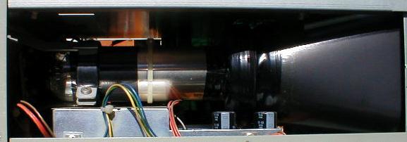
On the inside:
 The inner workings of this DSO. As you can see, 20 years ago they had a totally different idea of total
integration. Lots of wires, connectors, power transistors, heatsinks, potentiometers, you name it.
The inner workings of this DSO. As you can see, 20 years ago they had a totally different idea of total
integration. Lots of wires, connectors, power transistors, heatsinks, potentiometers, you name it.
There are 5 or six full size fully populated printed circuit boards in this instrument.
Take a look at the printed circuit board on the far left. These t4races are not produced by a CAM system. The
roundness of the traces indicates that this board has been manually routed.
On the other side:
 On the left of the picture we see the power supply section. It is based on an ILP toroid transformer, on top
of which a printed circuit board holds a series of electrolytical capacitors. On the side, as you can see at
the far left, are 5 TO-220 cased voltage regulators. Two 7805's, Two LM 317's and another. All mounted on the
same heatsink.
On the left of the picture we see the power supply section. It is based on an ILP toroid transformer, on top
of which a printed circuit board holds a series of electrolytical capacitors. On the side, as you can see at
the far left, are 5 TO-220 cased voltage regulators. Two 7805's, Two LM 317's and another. All mounted on the
same heatsink.
The printed circuit board on the right side shows some scorch marks. Apparently, some component died there. A
closer look at the other side of the board shows that there now are two fairly recent power resistors.
Apparently they caused the fire. The ubiquitous ground loop?
Did it throw up?
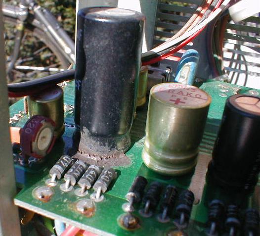 The big black cylinder is an electrolytical capacitor. They are notorious for their side effects such as
rupturing and dehydration.
The big black cylinder is an electrolytical capacitor. They are notorious for their side effects such as
rupturing and dehydration.
In the first case, the internal pressure builds up and eventually the cap bursts open, releasing a rather
nasty sludge of electrolytes.
In the second case, the cap looses water and dries out. Thereby loosing capacitance and hence starting to work
less.
Take a look at the bottom of the black cylinder. There is a strange black debris. It might be signs of a
slowly rupturing capacitor. But it can also be old glue. In many cases, bigger parts are glued to their PCB's.
And that glue will deteriorate in time.
There is also a strange smell near the capacitor section. And the contact pins of the diodes (the four black
thingies in the foreground) look corroded. These are all signs that the capacitor is att least leaking. So I
will take this section apart and replace the capacitors with fresh ones.
Sample and hold
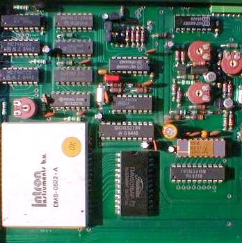 On the left, we see the big printed circuit board that is above the CRT. It contains the full sample and hold
section, plus the digital control section. My untrained eye revealed two IC's of type 2016 and two IC's of
type TRW 8351.
On the left, we see the big printed circuit board that is above the CRT. It contains the full sample and hold
section, plus the digital control section. My untrained eye revealed two IC's of type 2016 and two IC's of
type TRW 8351.
The 2016 is a fast static RAM memory chip of 2048 bytes. There are twp of this in the system so I guess each
channel has 2048 samples.
The TRW 8351 is a strange critter. I cannot find anything about it, but I estimate this is some kind of simple
processor. It is connected with a bus structure. You can find these chips easily since they are in a ceramic
DIP package (18 pins) with a gold lid on top.
Elsewhere on this printed circuit board are at least one DAC and an ADC. The ADC is in the white package at
the far left. The box is labeled 'Intron instruments bv' which is an indication that major parts of the scope
were made or designed in The Netherlands. A company called 'BV' is similar to a Ltd or GmbH in english or
german countries. Still, I cannot find anything on the internet...
As you can see, the board is littered with TTL integrated circuits. All of the Low Power Schottky (abbreviated
to 'LS')
 It looks like each channel has its own processor and memory. Why the DAC is on board, I'm not sure.
Probes:
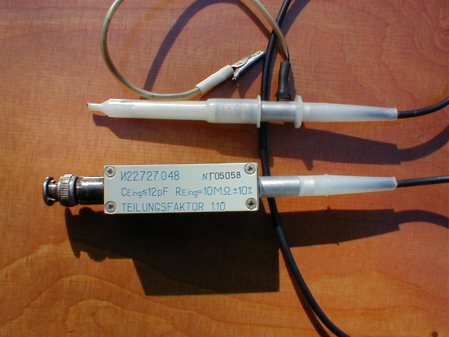
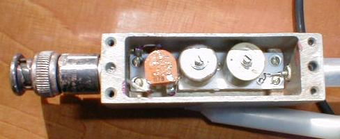 Above, you can see the original probes that came with the scope. These are very old probes. The metal box
contains two trimmers and a gobbledygook for the calibration.
Above, you can see the original probes that came with the scope. These are very old probes. The metal box
contains two trimmers and a gobbledygook for the calibration.
I think I will have to donate these probes to some museum. Better probes can be bought for reasonable prices
and I still have the probes that came with my Hameg. The picture on the right shows the inside of the metal
box.